Author: Carlo Cappellani – Senior Geoscientist
Introduction
Hydrogen will play a key role in the development and transformation of future renewable energy systems.
H2 has many benefits, can be generated by well-established and emerging technologies and can be used in a variety of end-use energy and transport processes. H2, as a fuel source, has long been identified as a critical step toward a low-carbon, and eventually zero-carbon, energy society.
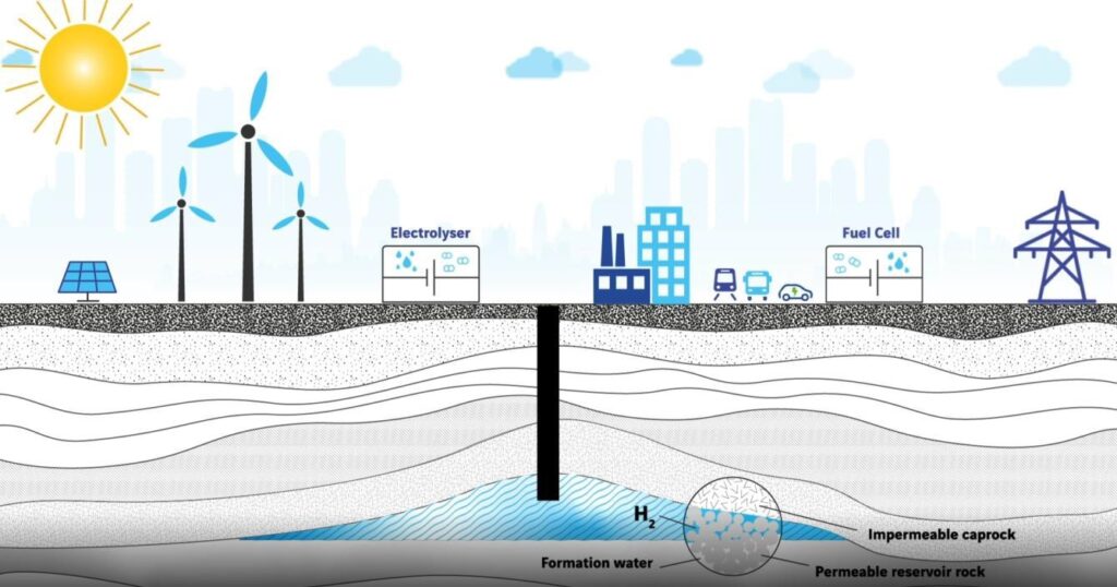
Hydrogen storage is an essential element of an integrated energy system and hydrogen economy.
As hydrogen demand and production are growing, underground storage is emerging as a relevant, large-scale solution. While in recent years a lot of attention has mainly been on hydrogen supply and transmission infrastructure, there is the need for underground hydrogen storage to balance and ensure the resilience of a future energy system that relies significantly on renewable energy sources.
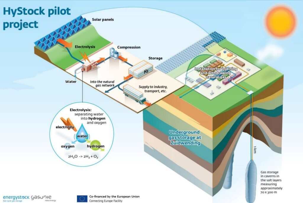
Hydrogen can be physically underground stored using a method which has already proven its worth and Carbon Geo Sequestration (CGS) and natural gas are essential analogs for H2 storage. Natural gas storage in underground facilities can be dated back to 1916 when it was stored in geological formations.
According to many authors, Ontario gas field (Canada) is considered the first successful underground storage project (Taylor et al., 1986). However, certain operational differences (physical and chemical properties) unique to H2 must be acknowledged for effective operation (Iglauer, 2017).
Higher demand means there is going to be a need for increased storage capacity and the solution to this challenge is to utilize earth underground reservoirs. Underground reservoirs, such as salt caverns or porous rocks, offer giant capacities to store billions of cubic meters of hydrogen at high-pressures.
Although the existence of few Underground Hydrogen Storage (UHS) sites, up till now, little is known about how hydrogen behaves in the subsurface and, current studies are investigating not only how it behaves in the subsurface but also what kind of environment – type of subsurface – would be the right reservoir to store it at a given quantity and scale. Also, to consider challenges of containing hydrogen tiny molecules inside the reservoirs, maintaining its purity, and operating the system within safe mechanical cyclic loading.
Considering underground hydrogen storage, an integrated multidisciplinary approach is required, combining several specialists and disciplines (e.g. fluid mechanics and rock mechanics, etc.). Also, integrating laboratory discoveries with numerical modelling will provide solutions to make this technology ready for field deployment within next year
Hydrogen underground storage and the hydrogen system
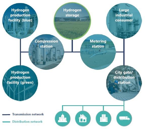
Underground storage will be critical to any large-scale hydrogen economy and the future hydrogen network could eventually operate the same way as the existing natural gas network. A network of pipelines will connect the hydrogen supply to a variety of customers of different scales and with different demand needs.
Underground hydrogen storage will provide a necessary tool, allowing operators to control the flows of hydrogen to meet the demands of all customers at any given time.
Underground hydrogen storage will enable operators to modulate supply and demand, maintain the integrity of infrastructure by keeping pressure and temperature within design parameters, ensure contractually obligated uninterrupted supply, insure against disruptions to supply and/or demand, and defer some additional investments into electricity infrastructure.
As it happens in natural gas system, supply and demand balancing will be required on all timescales— hourly, daily, weekly, and seasonal. Compared to its current use, the role of underground gas storage will be even more pronounced to ensure the resilience of the energy system as a whole. Whereas natural gas systems can partly rely on other storage (e.g., liquefied, compressed aboveground storage) and balancing methods, aboveground hydrogen storage is not feasible for large-scale applications.
Hydrogen above ground storage would either have an immense footprint or be very energy-intensive, or expensive or will require additional infrastructure. Alternative ways of storing energy might be complementary to the deployment of underground hydrogen storage.
Batteries and pumped hydro are more mature technologies, whereas liquid air energy storage or compressed air energy storage present newer alternatives. All of these could be utilized for the short-term balancing of power supply intermittency, either directly for the electricity system itself or when coupled with green (electrolytic) hydrogen production. Longer-term balancing for both hydrogen and electricity systems will most likely have to utilize underground hydrogen storage given the combined needs for power rating and discharge time.
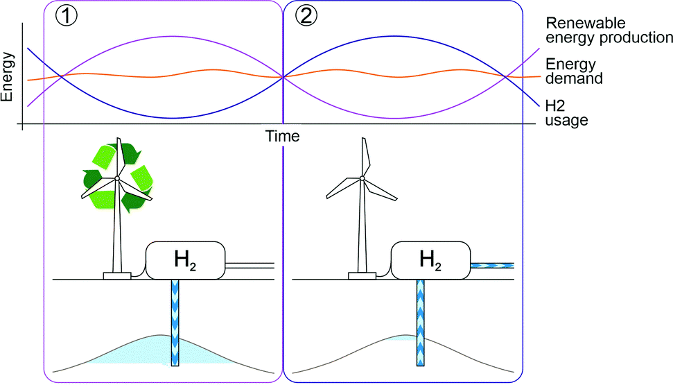
Due to the decentralized and intermittent production of hydrogen, the hydrogen system will have a greater need for flexible storage that can quickly respond to short-term fluctuations. There will also be seasonal variations in supply, the magnitude of which will depend heavily on the sources of hydrogen in a particular region.
An important difference between the hydrogen system and the natural gas system is that most of the hydrogen’s volatility comes from supply, and demand will be relatively constant. This may mean a preference to locate hydrogen storage close to hydrogen production rather than demand. Ultimately, the type and exact location of storage sites will likely be determined by the geographical availability of suitable underground (geological) structures.
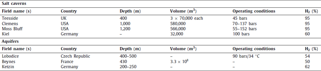
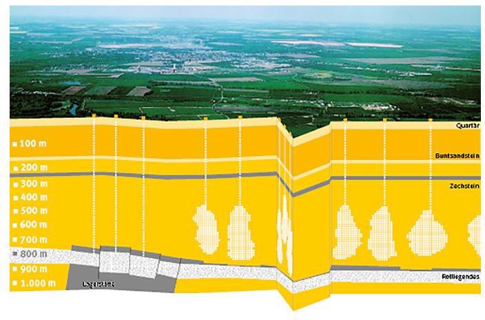
Globally, successful H2 storage in underground geological formations is limited to the caverns and aquifers. A British company’s salt caverns in Teesside, UK, successfully stored H2 95% H2 and 3%–4% CO2) at a depth of 400 m, whereas Conoco Phillips’ salt caverns on the US Gulf Coast in Texas, successfully stored H2 (95% H2 and 3%–4% CO2) at a depth of 1000 m.
The Kiel town gas project in Germany represents the salt cavern H2 storage facility that has been recorded, with a 60% capacity. On the other hand, the aquifer projects cases reported are Ketzin in Germany, Lobodice in the Czech Republic, and Beynes in France.
Current underground gas storage is typically capable of switching between injection and withdrawal cycles in an hour or a few hours. Demand created by fluctuations in supply or demand in gas often occur quicker than this, sometimes with only minutes of warning. To bridge the gap between the changes in demand and storage activation time, operators can use storage netting or pipeline line pack.
In a natural gas system with hundreds of kilometers of pipes, the line pack can be sufficient to bridge the time gap between the demand and the activation of the storage.
Hydrogen networks with underground hydrogen storage should be able to meet these flexibility requirements assuming they could be operated in a similar way to natural gas.
Some existing underground gas storage sites will need to be repurposed for hydrogen, while new storage sites might be developed as well. The decision for repurposed versus new development will be driven by a variety of factors including specific hydrogen and natural gas storage needs, availability, and the individual suitability of the storage site.
For current gas storage assets to be repurposed, a suitable incentive will be needed. This incentive includes recognizing and funding R&D costs associated with the investigation of a site’s suitability for hydrogen, a clear regulatory environment (e.g., rules for hydrogen blending), and a positive business case (demand) that would justify the repurposing.
FORMS OF HYDROGEN FOR UNDERGROUND STORAGE
There are few forms in which hydrogen can be stored in the subsurface and the choice of the proper one mainly depends on
- The type of energy used initially for the production
- The form of the final energy consumed
- The methods of energy conversion
Objectives and methods of UHS strongly depend on the interaction of all of these aspects. For ex.:
if the goal is to store pure H2 and use it in fuel cells later, any chemical modification of H2 during storage should be avoided.
if the H2 is to be used in gas-fired turbines or injected into natural gas pipelines, the addition of methane or other energy carriers to the stored gas is likely to be considered.
The main forms in which hydrogen is underground stored are:
- Pure H2
Only the pure form of H2 is stored underground and the destination of the final form of the pure H2 is fuel cell application (Panfilov, 2016). The pure H2 is mainly produced through chemical or thermal electrolysis from the excess renewable electricity or from the nuclear plant
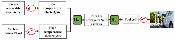
The stored H2 is extracted and reconverted via an electrolyzer during periods of increasing demand, and then converted back to electricity in fuel cells which is applied in vehicles.
The convenient storage sites for ultra-pure H2 shall guarantee a very low risk of potential gas contamination by impurities (e.g., Salt caverns)
- Mixture with natural gas in H2
This form of H2 storage is applied for transportation purposes, especially when a long distance between the production site of the CH4 gas and consumer market is less than 2000 km (He et al., 2019). Pure H2 is produced before injecting into an underground site containing natural gas for transportation.
The current standards allow only a small amount of H2 (6 to 15%) so that the energy potential of the stored gas is not reduced substantially (Panfilov, 2016). The integrity of the gas transport system (pipeline) is not affected by H2 embrittlement.
H2 and CH4 could also be separated before consumption (if needed).
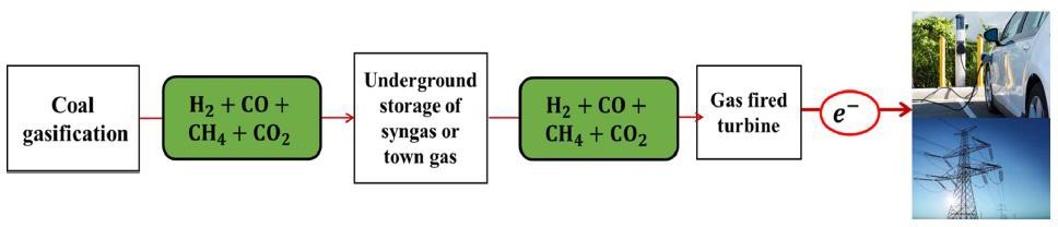
- Rich H2 mixture with CO, CH4 and CO2
Rich hydrogen mixtures with CH4, CO, and CO2 are produced from superficial or underground coal gasification. This can be in the form of syngas (mixture of H2 (20-40%) and CO) or town gas (mixture of H2 (50-60%), CO and CH4). The latest version of coal gasification allows about 70% H2 for the mixture and it can be consumed in two forms: (a) as electricity in gas turbines via thermo- mechanical conversion and (b) as fuel for lighting and heating. There are already sites where this hydrogen forms have been underground stored such as salt caverns (Teesside, UK; Kiel, Germany) and aquifers (Beynes,France; Lobodice, Czechoslovakia)
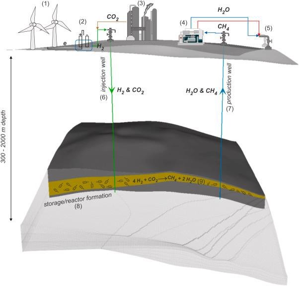
- Underground methanation reactor (UMR)
UMR represents an H2 mixture with CO2 in the presence of methanogenic bacteria. Microbial methanation was observed as a side effect during these gas storage operations, and the concept of underground bio- methanation uses the microbial metabolism to convert hydrogen and carbon dioxide into methane. The concept consists of injecting gaseous hydrogen and carbon dioxide into an underground structure (aquifers or depleted gas reservoirs) during energy production peaks which are subsequently partly converted into methane.
Underground H2 methanation can occur at low temperatures due to bacteria. It is potentially more cost- effective than the current commercial process which uses high temperatures and expensive catalyzers
(Panfilov et al., 2016). Furthermore, the CO2 proportion injected is completely converted to CH4; thus, UMR resulting gas is injected into a grid of natural gas and is used as fuel.
HYDROGEN UNDERGROUND STORAGE SITES
Generally, an underground gas storage (UGS) facility is an artificially created accumulation of gas in the natural environment at a significant depth in the subsurface: it consists of the working gas and the cushion gas.
The working gas (H2 in this case), is the total amount of gas that is injected and subsequently made available to customers after withdrawal. It is one of the two operation specifications in addition to deliverability rate (i.e., injection and withdrawal rate of gas) that characterized the reservoir.
The cushion gas (e.g., CO2, CH4, N2, and even H2 itself) represents the unextracted volume of gas that serves as a buffer for management purposes and pressure maintenance (Amid et al., 2016) during injection and withdrawal cycles (Lord et al., 2014). It prevents water from entering the stored compartment to enable optimum storage space (Tarkowski, 2017).
UHS sites are grouped into
Conventional
- salt caverns
- aquifers
- depleted hydrocarbon reservoirs
Non-conventional
- abandoned coal mines
- lined hard rock caverns
- refrigerated mined caverns
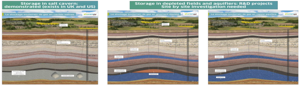

Conventional UHS
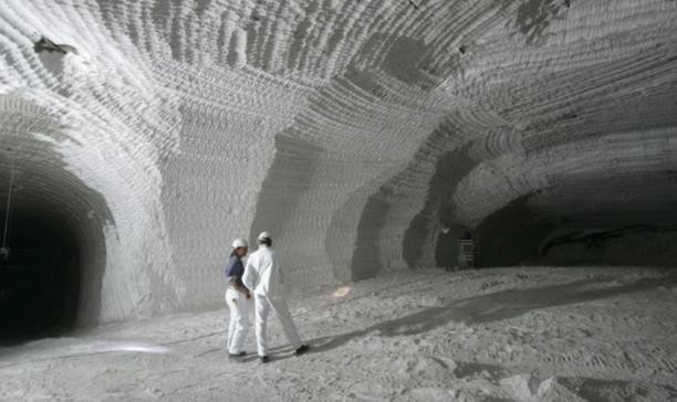
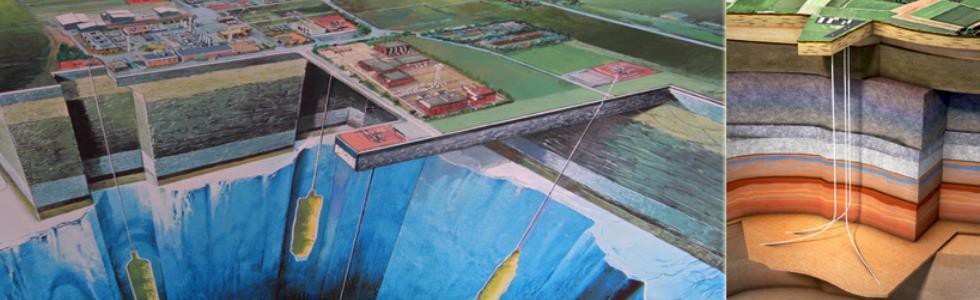
Salt caverns
Salt caverns are artificial structures constructed in underground rock salt formations. To construct salt caverns, water is injected underground, dissolving the rock salt: solution mining (Lemieux et al., 2019) is the name given to this essential process. The resulting brine is extracted and disposed of, leaving an underground cavity that is completely enclosed in salt. Surface and subsurface infrastructure must also be purchased and installed. Salt caverns can be created in either salt domes or bedded salt formations.
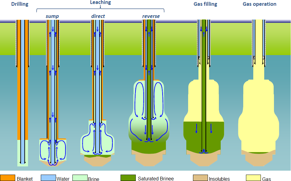
A typical salt cavern can be up to 2000 m deep, 1,000,000 m3 volume, 300 to 500 m height, and 50 to 100 m diameter, allowing for massive storage amounts (Michalski et al., 2017) and a pressure window (30-80% of lithostatic pressure Stolten and Grube, 2010). Pressures can range from 35 bar to 210 bar, but typical operating pressures are around 80-120 bar.
Caverns’ long-term structural stability and serviceability depend on their material heterogeneity and complex geometries (Kumar et al., 2021), thus, understanding their influence on the state of stress is essential. Also, they undergo a non-linear creep deformation due to the longterm loading effect caused by underground storage (Kumar et al., 2021).
Caverns are often regarded as the best option for UHS due to their low gas permeability, good rheology — which contributes to excellent sealing strength, and ability to redistribute stresses via viscous-plastic deformation (Lemieux et al., 2019).
Due to the high salinity nature, caverns may not be affected by insitu biological activities of microorganisms because microbes’ activities are ineffective at this condition (Gregory et al., 2019; Jaakkola et al., 2016): optimal option for pure H2 storage.
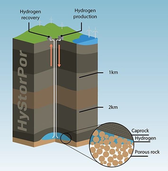
Aquifer
An aquifer is a subsurface layer of permeable and porous rock that is filled with fresh or saline water and is often hundreds of feet deep. The storage mechanism for aquifer is characterized by porous and permeable rocks. However, basic geological requirements must be satisfied, such as (i) the host rock for injection has good reservoir properties, and (ii) the host rock for injection has good qualities to prevent the migration of the stored gas (Tarkowski, 2019).
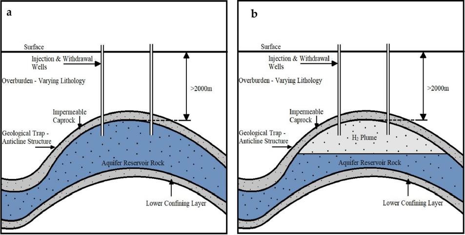
A suitable aquifer for storage may have geology similar to a depleted gas reservoir and requires a trapping structure (i.e. anticline) for the injected gas. The aquifer should have adequate porosity and permeability and sufficient storage capacity. Aquifers are often more expensive to develop than depleted reservoirs due to uncertain geology and lack of infrastructure.
Geologic characteristics of undeveloped aquifers are commonly uncertain, and data must be acquired to confirm injectivity and containment. Cushion gas requirements for aquifers are greater than those for depleted reservoirs because there is no naturally occurring gas present to offset the total volume needs.
The amount of cushion gas required may be as high as 80% of the total reservoir volume. This is a large proportion of the initial storage cycle, but small when averaged over many cycles. There are also options to use other less expensive gases as part of the cushion gas e.g. nitrogen.
Some loss of gas is inevitable and can occur through loss of hydrogen to cushion gas (unrecoverable), escape via leaky wells, and dissolution or diffusion into formation water.
Sulphate and carbonate-containing minerals can result in the production of contaminants, so this must be studied and accounted for during hydrogen storage development. Water is a common impurity in gas stored in aquifers, so gas drying infrastructure is an important component of the gas treatment process.
Other factors impacting aquifer UHS operation include undetected leakage (migration) along faults and H2 reactivity with minerals in the reservoir rock.
Hydrogen storage in aquifers has not yet been tested on the ground. However, the Lacq Hydrogen Project plans to use one of Teréga’s aquifers for hydrogen storage. The project should be operational by 2026. Enagás (Spain) is also investigating the feasibility of storing hydrogen in its aquifers.
Depleted oil and gas reservoirs
It is the most common option for underground natural gas storage (UGS) to date. They have demonstrated containment because they have trapped natural gas over geological time scales. These sites offer adequate storage capacity (i.e. high porosity), adequate injectivity (i.e., high permeability) and safe containment in the form of an impermeable caprock along with a geologic structure to contain and trap gas.
The operating pressures are limited by two geomechanical processes: (a) the tensile fracture pressure of the reservoir rock, (b) the stresses at which faulting or other mechanical damage may be induced in either the reservoir or the caprock (Bruno et al., 1998).
Also, hydrogen’s higher compressibility factor, diffusivity, and lower viscosity must be considered (it may be more difficult to contain than natural gas).
Non-conventional storage options
Abandoned coal mine
Abandoned coal are being investigated as prospective gas storage sites (e.g., CO2 and CH4) (Jalili et al., 2019) as they might be appropriate for H2 storage too. The amount of natural gas that may be stored in a coal mine is determined by the adsorption rate of the unmined coal as well as the volume mined.
The mining history and geology surrounding the mine are critical for a coal mine to be appropriate for natural gas storage because they inform the required pressure and strategy for the operation.
The mined coal seam must be protected by an impermeable layer to achieve successful gas trapping and the pressure at which the mine may operate is determined by the geology and surrounding hydrostatic pressure (Lord, 2009).
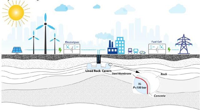
Lined hard rock caverns
Hard rock caverns are the newest of the main underground storage technologies. Hard rock caverns are artificial structures consisting of caverns created in metamorphic or igneous rock. The caverns are lined with a layer of concrete to create smooth walls, which are then lined with steel or plastic.
Because they are carefully crafted and lined, hard rock caverns have no risks of impurities and can be operated at higher pressures than the other structures. They can also experience several injection and withdrawal cycles per year, making them well-suited for peaking purposes. Also, they require relatively little cushion gas.
Hydrogen has not yet been stored in a hard rock cavern; however, a lined rock cavern is being developed by SSAB, LKAB, and Vattenfall as part of the HYBRIT green steel project. The rock cavern is expected to become operational in 2022. Hard rock caverns will likely be suitable for hydrogen, but they will likely be reserved for peaking facilities in geographies with no other storage options because they are costly to develop. One potential concern with steel-lined caverns is that long-term exposure of steel to hydrogen can cause hydrogen embrittlement. This implies that a higher grade of steel or another kind of liner may need to be used.
Refrigerated mined caverns
The high economics involved in construction and installations of lined hard rock caverns is leading to consider a less expensive storage solution: refrigerated mined caverns.
In this technology, the gas is chilled to a specific temperature before being placed into storage. The effect of cooling brings about compression and reduction in temperature (cryogenic) which results in less storage volume. It is reported that gas cooled to −40◦F will require less storage space because the volume is reduced by 50% (Lord, 2009).
They have good storage potential, a lot of flexibility, cycle capacity, and a large delivery rate. They are also thought to be the optimal storage solutions in locations where salt deposits are not present.
Because refrigerated mined caverns are not lined, igneous and metamorphic rock is preferred and they must be self-supporting and impermeable. There should be no faults, joints, or shear zones in the primary (host) rock (Freeway, 1998).
The required amount of cushion gas hugely depends on the depth and since the design of a refrigerated mined caverns is limited to a depth range of 2500 to 3000 m, minimum cushion gas is required to maintain the pressure of the stored gas through fissures and crack to reduce the water influx from the surface.
SUB-SURFACE AND SURFACE INFRASTRUCTURES: COMPONENTS AND CHALLENGES
All underground gas storage has surface and subsurface infrastructure used to connect the storage to the grid: wells, piping, compressors, and purification infrastructure. For hydrogen repurposing, the kinds of equipment required are more or less the same.
Studies are ongoing to determine the necessary changes to infrastructure and associated costs. First estimations assume that retrofitting existing storage sites to pure hydrogen storage will cost around 20%- 30% of the cost to construct a new storage site. Hydrogen and methane have different physical properties and likely different purity requirements; thus, parts of the existing infrastructure will have to be modified or replaced, including compressors.
Hydrogen can cause embrittlement of steel over prolonged contact, so all materials need to be tested for compatibility.
Different types of storage have different possible impurities, so the gas treatment infrastructure varies. It has not yet been determined how much of the existing gas purification infrastructure from natural gas storage can be used for hydrogen or how much it will cost to replace what needs replacing.
UHS techniques show some challenges because the experience on this technology is limited. Some of these factors (finances, governmental policies, engineering, legal and social) are adjustable whereas some are rigid (geology-related). It becomes essential to ensure all these issues are put into perspective for an effective UHS operation.
Broadly, the main challenges related to UHS can be described as subsurface and surface challenges.
Subsurface challenges are mainly related to the fluid flow behavior of hydrogen in subsurface reservoirs, geochemical reactions caused by hydrogen injection, biotic reactions caused by excess hydrogen, and the geomechanical response of the subsurface to hydrogen storage and well integrity.
Surface challenges are mostly related to the processes and units which support the whole technology such as compression, purification, etc.
Hydrogen properties
Hydrogen is the lightest and the most plentiful element in nature and can exist in various states depending on the applied temperature and pressure. Hydrogen does not exist in a pure form in nature and, therefore, has to be produced. In the subsurface, hydrogen is stored as a compressed gas, at high temperatures and pressures. Contrary to most gases, hydrogen warms when expanded at constant enthalpy at atmospheric pressure and room temperature. This phenomenon (called the Joule-Thomson effect) may prevent the formation of water vapour and dehydration process in the surface facility with no thermodynamic challenges for UHS. The actual magnitude of this effect depends on the Joule-Thomson coefficient, which is
Differences with natural gas exist and they are summarized in the table below:
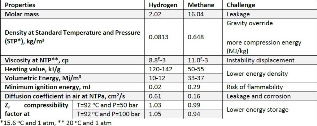
These unique properties make the storage of hydrogen more challenging compared to natural gas. The depth of storage in geological structures depends on the phase behaviour of gas. The trend of hydrogen and natural gas viscosity is similar; therefore, such parameters do not influence the choice of the storage depth between hydrogen and methane.
Subsurface challenges
Hydrogen energy deliverability
Due to hydrogen properties, the storage capacity for hydrogen is lower than methane or natural gas.
The figure below compares the storage capacity of hydrogen and methane at different pressure and temperature and it shows that in the reservoir condition, the storage capacity for hydrogen is 80%-85% of methane.
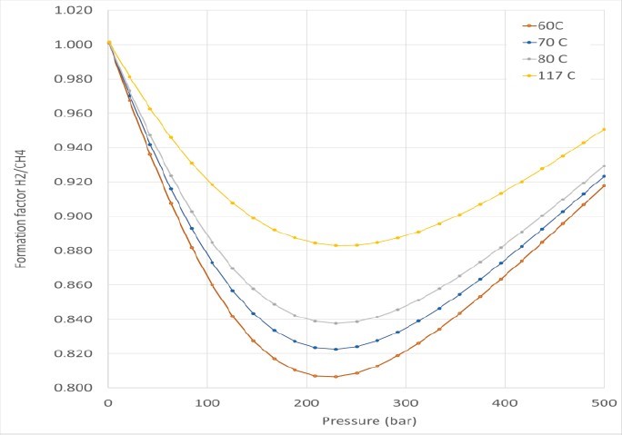
The volumetric energy of hydrogen is one-third of methane, the energy deliverability of hydrogen (J/sm3) is only 25%-30% of methane. This is one of the drawbacks of using hydrogen as a source of energy.
Geochemical reactions
Geochemical reactions of hydrogen with rock minerals are slow processes. However, their effect should be studied in the time scale of gas storage operations and the possible petrophysical effects such as a change in porosity and permeability should be considered.
Some consequences of geochemical reaction are:
- Conversion of H2 to H2S can occur (by sulfate-reducing bacteria or sulfur-containing minerals)
- Dissolving hydrogen in water leads to an acidic solution, which will corrode underground equipment and rubber
- Free CO2 in residual gas or CO2 in carbonate rocks can react with H2 to produce
- Porosity and permeability changes due to alteration, dissolution and precipitation of minerals
Biochemical conversion processes
Microorganisms are able to live under reservoir pressure and temperature. In the right conditions (not too high temperature and salinity), the activity of different types of bacteria is likely, and they can consume hydrogen and may lead to hydrogen loss or the formation of impurity in the fluid stream.
The main issues related to biochemical conversion processes are:
- corrosion and acidification of the reservoir fluids by H2S
- permeability reduction with iron sulfide (FeS) precipitation
- decreasing gas quality by hydrogen consumption and impurities formation
Hydrogen loss due to diffusion
Although no severe problem has been yet reported for town gas storage, it is not clear whether the sealing, which managed to preserve oil and gas over geological timescales, can also prevent hydrogen losses.
The diffusion process through cap rock is possible when hydrogen dissolves into the brine. The hydrogen solubility in water is lower than the methane solubility. However, the higher diffusivity of hydrogen makes the process faster.
Hydrogen mixing with residual gases
In case of UHS in depleted gas reservoirs, injected hydrogen into the reservoir could mix with residual gases such as natural gas, CO2 and N2.
In the withdrawal mode hydrogen is produced with some impurities and there is a need to purify the gas stream according to the end-user requirements. This issue doesn’t happen in salt caverns where only a dehydration unit is required to separate the water and water vapour from hydrogen.
Hydrogen interaction with brine
The hydrogen interaction with brine should be studied to predict hydrogen solubility in the water and its effect on the reservoir fluids flow during the storage. Prediction model must be used, but generally, higher salinity, higher temperature and lower pressure lead to lower hydrogen solubility.
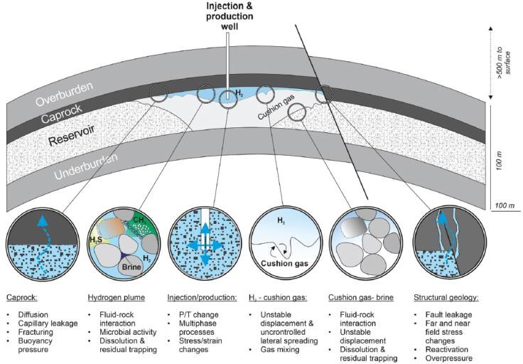
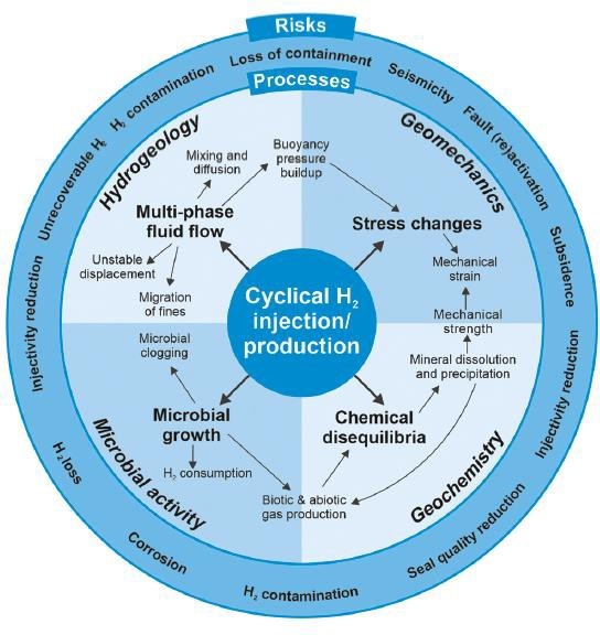
Below, two summary sketch showing geo-uncertainties and aspects of the UHS:
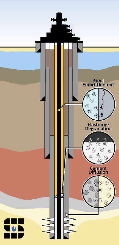
Well Integrity
Wells must endure the stresses created by site operations and always maintain their structural integrity. Wells that lose control of injected or extracted fluids may become a human health or environmental hazard if the injectate is leaked into the atmosphere or groundwater in significant quantities.
Maintaining the integrity of wells at UHS sites may be uniquely challenging because of the intrinsic properties of H2 and the subsurface environment created by injection operations.
The design of borehole equipment in UHS such as casing, tubing, cement, and packer is important in porous reservoirs due to hydrogen high diffusivity and its contamination with other substances (geochemical and biochemical reactions).
The potential risks related to well integrity are:
- Integrity of materials under exposure to hydrogen:
This includes the impacts of hydrogen on the materials such as hydrogen blistering, hydrogen- induced cracking (HIC), and hydrogen embrittlement. The metal exposed to hydrogen could be damaged due to tensile stress fluctuations in the tubing and the cyclic operation of storage. Corrosion-resistant alloys with an austenitic structure can decrease the harmful impact of hydrogen on the subsurface equipment. In principle, hydrogen-related material damage may be prevented by appropriate coatings (ref. 1), which act as a barrier to H2 diffusion. Recent results show that novel surface treatment methods of iron may be available in the next future, (ref. 2) namely helium implantation or ion irradiation.
Also, the diffusion process through cement, chemical alteration of cement and integrity loss of elastomer packer should be considered in completion design.
- Integrity of materials under exposure to corrosive fluids and H2S:
Corrosion caused by an acidic solution such as hydrogen sulfide which can decrease the service life of the downhole equipment (e.g.elastomers). H2S is highly corrosive and the API standard specification should be considered for the type of metal.
- Microbial-induced corrosion:
The microorganism in the reservoir can attach to the surface of metals and form and develop a biofilm in which they consume nutrients and produce polymer substances. They lead to localized corrosion in the steel. Proper selection of material based on the operative and environmental conditions in the reservoirs is necessary.
Surface challenges
Every gas storage system consists of an injection phase (storage) and a delivery phase (withdrawal) and the two main components of storage facilities are compressors for gas injection and separators and dryers for withdrawal. Other facilities are gas measurement units, station piping, pressure control unit and pre- heating system (if needed).
Hydrogen compression and compressor types
The compressor in surface facilities is used to increase the inlet gas pressure from the transmission pipeline to then be injected into the underground reservoir. The level of pressure increase depends on the depth and reservoir properties. The compressor also can be used to pump withdrawal gas to the pipeline and
separation unit in the withdrawal process. Due to varying conditions of storage in the operation, the compressor should work on a broad range of volume and pressure.
The lower density and higher compressibility factor of hydrogen lead to more compression energy (MJ/kg) for hydrogen compared to methane and helium.
The pressure increase during the compression generates heat leading to temperature increase of the discharge gas. Therefore, a heat exchanger (cooler) is required after each compression stage. The cooling stage decreases the gas volume moving to the high-pressure cylinders, reduces the work needed for the next step and keeps the temperature within safe ranges.
As hydrogen could react with glycol to form water, using glycol as a coolant for machines is not suggested.
Reciprocating and centrifugal compressors are the most common types of the compressor for gas storage projects. Based on the current technologies, only reciprocating and centrifugal compressors could be used for large-scale underground storage projects.
As general rules, Turbo (centrifugal) compressors are used for high rate and low-pressure ratios. Whereas, reciprocating (volumetric) compressors are suitable when lower rates and higher-pressure ratios are needed. Due to the low molecular weight of hydrogen, a reciprocating (positive displacement) compressor is a better choice than a centrifugal one in order to gain better efficiency
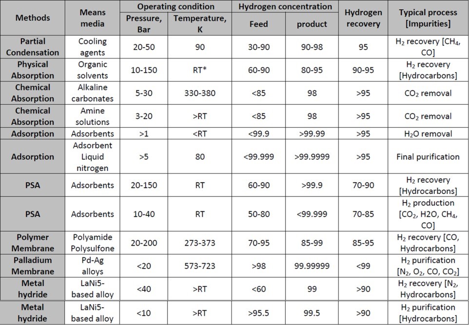
Hydrogen purification
The purity requirement varies with the application of hydrogen in the industry. For example, a hydrogen fuel cell requires high hydrogen purity to prevent catalyst deactivation where other sectors such as built environment or power generation can tolerate with lower hydrogen purity. The most important impurities are N2, natural gases, CO2, H2S and water. The method for hydrogen purification can be selected based on the gas feed composition, pressure and temperature, gas flow rate and end-user requirement. The most common methods are just compared below.
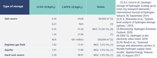
ECONOMICS OF UNDERGROUND HYDROGEN STORAGE
UHS is expected to be the most cost-effective option when the LARGE volumes of hydrogen need to be accommodated.
Cost estimates can vary depending on
- the type of storage (salt caverns, depleted hydrocarbon reservoirs, aquifers or hard rock caverns)
- the storage reservoir’s size
- the location and the utilization (including the charge/discharge frequency)
- the stored volume per cycle
- the rate of delivery
The major cost components for developing underground storage are cushion gas, site exploration and development, compressors, and other surface and subsurface infrastructure.
The table below summarizes some findings. NOTE: these estimates are based on literature with a set of assumptions about the storage specifics and the way the storage could be operated (e.g. the number of cycles), which all influence the calculated levelised cost of storage (LCOS).
The summary should not be seen as a comparison between different types of storage (that is too premature), but rather an indication of the order of magnitude of the investment and levelised cost.
The costs presented here must be treated with care and the original assumptions need to be assessed before applying these estimates elsewhere to determine UHS costs
Capital costs of UHS
For UHS in salt caverns capital investment is required for solution mining for cavern creation, including brine pipelines and lagoons, and injection/withdrawal borehole(s). Cushion gas to maintain a minimum storage pressure is also considered a capital investment since it remains in the cavern permanently (Taylor et al., 1986; Tarkowski, 2019), though in salt caverns it may be recovered by brine displacement at the end of a discharge cycle (Taylor et al., 1986).
Tarkowski (2019) estimated the capital cost structure as 60% gas compressors, 29% solution mining, 6% borehole, 5% cushion gas. Energy Technology Institute reported that the largest cost element in the construction of the cavern is the borehole. For storage in salt caverns no mineralogical or microbiological reactions are expected (Buenger et al., 2016).
The costs to develop a salt cavern for UHS are expected to be much higher than for depleted hydrocarbon reservoirs (Taylor et al., 1986; Crotogino et al. (2010); HyUnder, 2014b) as UHS in aquifers and depleted hydrocarbon reservoirs uses the existing pore volume as storage space. However, aquifers will require extensive characterization to ascertain hydrogen can be safely contained, the costs of which are difficult to estimate and will vary by site (Lord et al., 2014).
A significant consideration in these storage reservoirs is also the cost of cushion gas since the cushion gas requirements are likely to be notably higher than in salt caverns. However, the need for hydrogen cushion gas would be reduced if (some) gas was already present in the form of natural gas.
However, Amid et al., (2016) suggested that the presence of natural gas in the reservoir will lead to some mixing of recovered hydrogen with other gas components and this may require an additional process step of purification.
In depleted hydrocarbon reservoirs, existing wells are expected to be used for storage, though the integrity of the cement barrier over time needs to be ensured to prevent hydrogen diffusion into the cement (Bai et al., 2014). Austenitic stainless steel may be used to extend the service time of the wellbore (Bai et al., 2014), though this increases the cost of the completion.
For storage in hard rock caverns more costly excavation is necessary to create the required storage volume, including lining of the cavern. There are also higher compressor costs, but the cushion gas cost is less than for depleted gas reservoirs.
Operating costs of UHS
Operating costs are the cost of energy and maintenance related to gas compression for storage and possibly boosting the pressure after withdrawal (Amos, 1998), as well as working gas losses estimated at 1- 3% per year (Barbir, 2013).
The ratio of operating costs to total costs depends on the type and the utilisation of the storage facility e.g. for long-term storage operating costs may only constitute a small fraction of the total cost of storage (Oy 1992; Carpetis, 1994; Amos, 1998; Crotogino et al., 2010)
UPCOMING PROJECTS AND INNOVATIONS
In the U.S.
Advanced Clean Energy Storage project (https://aces-delta.com/) a joint venture between Mitsubishi Power and Magnum Development, will take excess power generated from hydroelectric, geothermal, solar and wind and electrolyse it into hydrogen for storage in the salt caverns, where it can later be used for power, industrial and transport applications. At 200 kilometers south of Salt Lake City, engineers are working on what will become the world’s largest storage facility for 1,000 megawatts of clean power, partly by storing hydrogen in underground salt caverns. Scheduled for operation by 2025, the first phase will provide 150,000 MWh of renewable power storage capacity — enough to power 150,000 households for one year.
In Europe
HYdrogen STORage In European Subsurface- Hystories: (https://hystories.eu/)– is developing a project whose final outcome will be assessments of techno-economic feasibility of implementing hydrogen storage in preferred locations, to enable informed decision making on pilot demonstration and industrial deployment.
Hydrogen Power Storage and Solutions East Germany (HYPOS) https://www.hypos-eastgermany.de/en/ government-funded German consortium of more than a 100 companies plans to build a salt cavern in Saxony-Anhalt with about 150,000 MWh of energy from wind power-generated hydrogen. The project aims to produce green hydrogen on an industrial scale, as well as to build an extensive network of distributor networks and storage stations across Germany to make hydrogen available to all regions.
HyUnder (http://hyunder.eu/) project will provide the first European-wide assessment of the potential for hydrogen storage in underground salt caverns to renewable electricity over the long term. The project will also analyse hydrogen storage interactions with the transport sector and other markets, while considering public acceptance and regulatory issues.
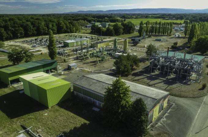
HyPSTER (https://hypster-project.eu/) Hydrogen Pilot STorage for large Ecosystem Replication is the first EU supported project for large scale green hydrogen underground storage in salt caverns. The demonstration facility will be located in Etrez, France. The project aims to use salt cavern storage to connect hydrogen injection by electrolysis to industrial and mobility uses. It will also test the technical and economic reproductibility of the process to other sites throughout Europe.
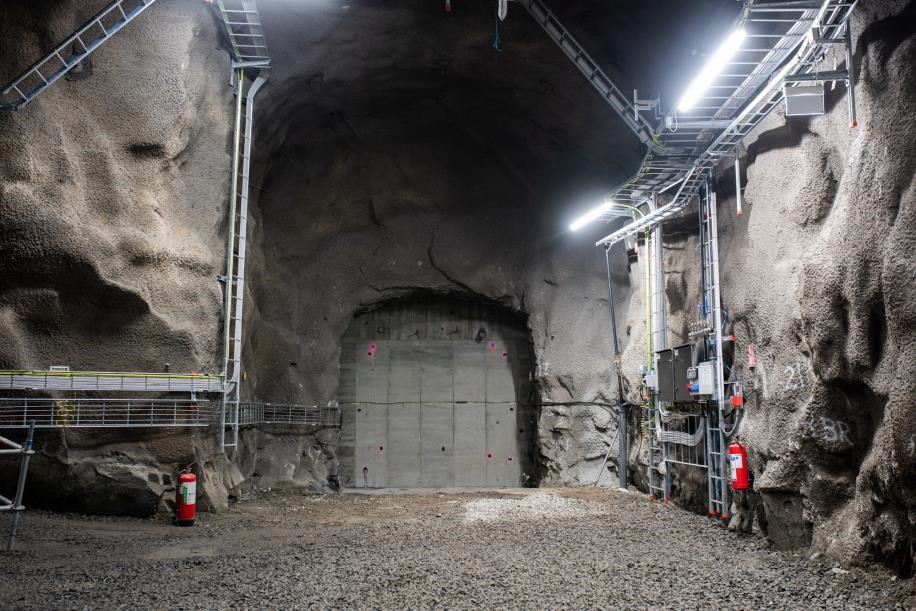
HYBRIT (https://group.vattenfall.com/) collaboration between SSAB, LKAB and Vattenfall. Construction of the rock cavern storage facility for fossil-free hydrogen in Luleå is near the end. The steel lining is being installed inside Svartöberget. The storage facility, which will be an important part of the value chain for fossil-free iron and steel production, is planned to be in operation by the summer (June 2022).
CONCLUSION
Large-scale hydrogen storage is required to face future challenges in terms of energy and the environmental transition. Hydrogen will be used primarily for industrial decarbonization, carbon-free mobility and carbon-free power generation. It will be used initially to decarbonize industry and mobility, for which underground storage will be required within a couple of years.
Underground pure hydrogen storage for power generation will also emerge, but large-scale demand may come later, in all likelihood after 2040.
The gas and power generation industries will use a methane-hydrogen mix, well before 2040. The methane- hydrogen mix will gradually reach 20% hydrogen, and possibly more, and will be stored underground, mainly in porous rock reservoirs.
Salt caverns will probably account for the largest share of underground storage needs, followed by porous rock reservoirs, especially for methane-hydrogen mixes. When the technology is ready, mined caverns will find their place in the value chain for international trading (ammonia, liquid hydrogen) or where pure hydrogen is to be stored in places without salt.
R&D efforts vary for these various techniques. Salt caverns and porous rock reservoirs are ready for commercialization, current research being aimed at furthering our knowledge and establishing standards. Demonstrators may be required here and there to address specific local questions and satisfy local decision makers, but no showstoppers have been identified overall.
Mined cavern techniques – for pressurized hydrogen, pressurized substitutes (such as ammonia) or liquefied hydrogen – will require a few years of technical developments. The corresponding caverns will be lined. Lined Rock Caverns (LRCs) for pressurized hydrogen or pressurized ammonia could be ready for commercialization in the near future. LRCs for liquid hydrogen present greater challenges owing to the very low temperature involved (-253°C).
These mined cavern techniques will remain more expensive than salt caverns and porous rock reservoirs. However, owing to their geological adaptability, mined cavern solutions will be needed to complete the hydrogen storage portfolio.
The economic viability of a particular storage site will depend on the integration of all aspects of the hydrogen value-chain, from production, to transport, to storage, to end-use. These features will also strongly affect the required storage volumes, and the frequency of cycling of the storage, which are both critical to the total cost of storage.
References:
- Sandeep Kumar Dwivedi, Manish Vishwakarma; Hydrogen Embrittlement Prevention in High Strength Steels by Application of Various Surface Coatings-A Review – Advances in Manufacturing and Industrial Engineering, 2021; ISBN: 978-981-15-8541-8
- Xu, Q., Zhang, J. Novel Methods for Prevention of Hydrogen Embrittlement in Iron. Sci Rep 7, 16927 (2017). https://doi.org/10.1038/s41598-017-17263-8